As many independent theaters operating on a budget, the next big gotcha is this timebomb spot-welded battery on your ICP board which conveniently houses your certificates for the rest of your cards in your Barco projector.
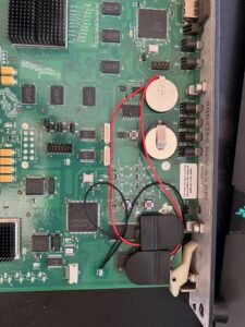
The ICP Board looks like this:
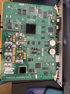
You'll notice the 2 batteries - one you can replace and one is spotwelded in place. I'm going to walk you through exactly how I replaced mine step by step - checking and double checking every step of the way.
Materials you'll need:
- Button cell holders with leads: https://a.co/d/fiu3FHw
- Soldering iron
- Solder
- Multimeter
- fresh new lithium battery: 2032, 2025 or BR2330
- wire strippers
- 2-sided tape / hot glue
- Dremel / small cutter
Note - The battery holders in that link have an off/on switch - I personally don't like this feature but just be aware of it. (more details later)
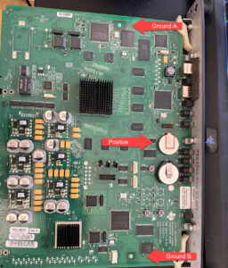
The Key points we'll be working with: Mostly positive and Ground B. - but Ground A is also a good spot if you'd like to mount the holder on the other side of the card near the pins where there's missing IC chips.
Step 1
Use your multimeter (DC Volts) to measure the voltage of the battery to both these ground pads to make sure you've got a good ground. Log this voltage on paper so we don't get it confused later.
I don't remember the exact voltage where the certs will get lots but if its under 3.0 volts you'll certainly want to consider swapping it.
Step 2
Go ahead and strip a little bit of insulation off the end, roughly 1/4" or 6mm. Install your new battery into your holder and test the voltage (remember that On/Off switch!) It should read roughly 3.2V.
If you see this, you can proceed. If you do not - test your battery is installed correctly, test the switch, test your multimeter is in the right setting.
Step 3 (optional)
I went ahead and tested a 2nd holder and a 2nd battery. I plan on swapping mine back and forth on a regular basis now that I have this setup. Repeat the steps on Step 2 if you want to run dual battery holders.
Step 4 (optional if you're running dual holders)
If you're doing the dual battery holder like I did, Twist the 2 red leads and the 2 back leads. (Remember to strip them to about 1/4"/6mm first.) You can remove one of the batteries at this step. We just want to validate the little holder is working as designed.
Step 5
Tin the wires. If you're new to soldering, you apply heat to the wires then tough the solder to the hot wires. If you do it correctly the solder will "wick" into the wires. Remove the soldering iron and hold the wires still for a moment to allow the solder to cool.
Step 6
Test the voltage again after the soldering. Pulling, straining, knocking them around, etc. We want to make sure we don't have a loose wire anywhere. Also layout where you want the holder(s) to be positioned. I put mine directly over the board print after I took a picture.
Step 7
Go ahead and add just a little solder to the ground pad that we will be attaching to. Repeat the steps above - you want to heat the work - not the solder. If you melt solder and it drips down onto the work it will not bond correctly. If your solder doesn't seem to be melting you may need new solder or a better soldering iron.
Step 8
Solder the BLACK lead to the ground pad B.
Step 9
ABSOLUTLEY CRITICAL - UNPLUG YOUR SOLDERING IRON
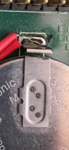
Tin the board where the spot welded battery comes in contact with it. Once you have a bead immediately solder the red wire to the fresh bead. (Right beside the battery post where the positive post touched the board.)
If your soldering iron becomes too cool to make this solder then remove it from the work - replug it in wait a few minutes and then UNPLUG it and retry.
Why are we unplugging it?
Some of the soldering irons have a direct connection to the metal heating element. That element is connected to your electrical systems ground. When the battery makes contact with another ground it can cause the voltage to drop on the cert chip and very easily erase your certs and you're right back to buying a new ICP board. Even if your soldering iron has a ceramic heater, don't risk it. Unplug it - trust me it works!
It should look like this:
Step 10
Measure the voltage from the spot welded post to the opposite ground you soldered (Ground A in my example). It should be somewhere between the original voltage and the new battery voltage (like 3.1V). If it matches the old voltage, something failed and you'll need to check your work (and the on/off switch)
DO NOT PROCEED until you figure out why it's not above the original voltage.
Step 11
Install the battery holders in their final spot using the 2-sided tape try to keep the wires tight but not pulling. You do not want the card above this one to catch a wire when being installed/removed. If you want to test the other holder, simply turn off the primary and install the battery in the 2nd. This is a great time too do so since you still have the old battery installed. Once your happy. Remove 1 battery and ensure the primary holder is ON.
Step 12
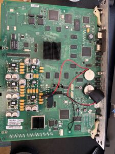
Using a dremel style took, cut the old battery so it does not drain the new battery
The final product should look like this:
Now the next time you need to swap your battery you'll take the following steps:
- Measure the old battery.
- Measure the new battery outside the holder.
- install the battery (ensure it's on! - do not the existing battery's switch)
- Measure to ensure you see a difference
- remove the old battery
- Measure the new installed battery.
